PGE Potrero Power Station Sediment Remediation

Location San Francisco, California
Contract Value $17,717,000
Period of Performance March 2019 – March 2020
Role Prime Contractor

Significant Project Features

  • Excavation and stabilization of 6,540 CY of sediment impacted by polycyclic aromatic hydrocarbon (PAHs) from the Offshore Sediment Area
  • Demolition of 120 LF of dilapidated steel bulkhead using a 5 to 7 man dive crew
  • Site restoration activities, including installation of capping material, reactive core mat placement, and riprap revetment
  • Over 31,000 safe workhours without a lost-time incident

History & Location Details

The Offshore Sediment Area is a subarea of the Potrero Power Plant Site located along the waterfront in San Francisco’s Central Waterfront Area. Historical upland site uses include industrial activities, a manufactured gas plant (MGP), and power plant activities while historical overwater site uses include dock activities (MGP wharf and sugar refinery wharf) and shipyard (immediately north of the Site). Although the shipyard slipways were later backfilled, concrete piers bracketing the shipways are still present and rails used for marine ship building are still present near the sediment surface. The site will be developed to support residential apartments, commercial office space, retail and recreational open space.

Project Description

Site Preparation

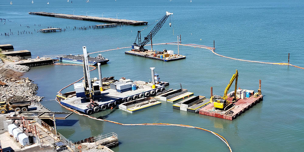
Before beginning the sediment removal, Sevenson established the staging area at the property, which consisted of a floating platform for water access, four turbidity curtains, temporary facilities including office trailers, erosion controls, decontamination features, fencing, signage, and utilities. A WWTP was already existing on the site from prior construction operations and was used for the duration of Sevenson’s construction activities. A survey was conducted of shoreline structures (topographic using mobile terrestrial laser scanner) and dredging areas (multibeam bathymetric). The topographic survey included all visible utilities along the shoreline as well as utility mark-outs. The bathymetric survey assisted in planning dredging operations and determining volumes. Surveys were performed during dredging and capping phases to verify completion of individual segments.

The Remedial Investigation (RI) Report (Haley & Aldrich, 2014b) presented several remedial action objectives (RAOs) to protect human health and the environment. The RAOs developed for the Offshore Sediment Area included mitigation of the potential for exposure of fish to PAHs that bioaccumulate in sediment organisms at concentrations greater than Ambient Area organisms and mitigation of potential future exposure of humans to impacted sediment within areas accessible to wading that may adversely affect human health. The RAOs were achieved by dredging and capping with clean materials near the shore, as well as placement of a reactive cap where needed.

1964 Steel Sheetpile Wall and Debris Removal

Limited information was available how the bulkhead was built in 1964. Sevenson’s original plan involved vibrating the sheets out. Once work began to remove the sheets with a 200 ton crane and a vibratory hammer, the sheets broke into pieces during attempted extraction. Sevenson quickly adapted to an approach to cut the sheets below the processed dredge template with a 5 to 7 man dive crew. Sediments were pulled back from the bulkhead face to allow divers to cut the sheets.

The 1964 steel pile was removed with a 200-ton crane working from land and debris was removed using a PC300 barge and Manitowoc 888 crane on a spud barge. Concurrently while the bulkhead demolition was progressing, debris was removed from the dredge areas prior to dredging operation. A PC300 and PC650 performed a majority of the work extracting piles by direct pull or breaking them off below the proposed dredge template.

Following the debris removal, field crews commenced the mechanical dredging of 7,500 CY of impacted sediment. Equipment utilized for dredging included a barge-mounted PC650 excavator with a 3.0-CY CableArm Environmental Level-cut clamshell bucket and a second spud barge measuring approximately 55×120-feet and drafting 2.5-feet. The eCrane was positioned on this barge for transloading operations from shore to land.

Mechanical Dredging

This project was divided into three distinct phases: Dredging began in Segment 2, then progressed to Segment 3, and the concluded in Segment 1. The following outlines the remedial activities executed in each segment.

Segment 2: A total of 4,385 CY of sediment was removed from this segment. Nearly half of the sediments were located below a four foot thick revetment that required stone removal and staging for re-use. Revetment removal was completed using a combination of PC300 long front on land and a PC650 on a barge. The PC650 performed a majority of the dredging in the offshore area in segment 2. Sediments were loaded into 100 CY hopper barges and transported with a shallow draft 600 HP tug.

Access/draft for the eCrane was dredged using the eCrane with direct loading into trucks. The eCrane staging area was dredged an additional one foot to allow for a one foot sacrificial sand cap to bridge the time span from when initial dredging was complete and the final cap would be installed. The sacrificial sand cap protected any residuals that might remain between when dredging started and when the final cap was placed after the eCrane was moved away from the unloading dock.

Segment 3: A total of 690 CY of sediment was removed from this segment of the site. Sevenson worked with the owner to identify and prepare a safe working distance when operating around four buried power lines. Structural rip rap areas were located outside of the dredging template and a minimum separation distance of 5-feet was included in the template design. Sevenson did not allow dredging outside of the template in this area and imported the structural riprap area to the dredge computer for the operator to visually avoid placing the bucket in that area.

Segment 1: Sevenson removed a total of 1,242 CY of sediment from this segment. In areas where the marine rails were present, full dredge depths could not be achieved. The environmental bucket was used to remove sediment to the maximum extent possible. Following dredging in marine rail areas, a thin layer of sand was placed on the post-dredge surface.

For all dredging operations, decanting operations were undertaken to remove excess water in the scow prior to transloading to water tight trucks staged onshore. A portable suction pump was used to convey water to a geotextile tube staging in a 20 CY roll-off dewatering box. Following the geotextile tube dewatering, the water was conveyed into frac tanks for storage prior to treatment in the Wastewater Treatment Plant.

Transloading was accomplished using the previously described eCrane and a material handling bucket. As noted previously, decanted and transloaded sediments were deposited into the sediment processing area using a dedicated unloading point and bin. Sediments were trucked from the bulkhead to the mixing bin, where they were dumped into a pit measuring approximately 50 feet long and 50 feet wide. Sediment processing methods involved the use of 1-ton Portland cement supersacks dosed directly into to the active mixing bin followed by mixing and homogenization. Once material was amended, it was staged to further dewater. After 1-2 days of additional dewatering and solidification, the materials were loaded into trucks and disposed off-site.

Capping Operations

Capping materials were delivered by dump truck and staged in the upland area. Capping materials included sand, stone, Reactive Core Mat, supersacks of AquaGate, and rip rap.

Sevenson conducted a field demonstration of cap placement means over a five-day period, at the beginning of the capping operations and prior to full-scale capping, The objective of the demonstration was to document achievement of cap design and layer thicknesses. The original plan was to use catch pans to verify the cap thicknesses, however the pans were problematic so Sevenson switched to a direct measurement approach using RTK GPS to verify thickness on a 10 f x 10 ft grid for each material type and layer.

A majority of the project required a reactive core mat prior to capping following dredging. Installing RCM in submerged areas was accomplished using a spreader bar attached to the PC650 and the 200 ton crane. The RCM was precut on lad, rolled back onto a spool and unrolled using the two machines. The two machines kept the mat on the water surface as it was natural saturated. The RCM was slowly lowered to the desired position by divers while coordinating movement of crane and excavator. The mat was anchored using sand bags.

As placement progressed, Sevenson had divers inspect placement of the RCM to verify location and seam overlap.

Multiple materials and variable thicknesses were placed to build the required cap. The materials were placed with the PC650 and a clamshell bucket. Materials were placed in a sweeping motion on the water surface releasing the materials in a controlled manner.

Rooted in Remedial Construction
Expanded into Environmental Dredging

Start a conversation about your upcoming project
(716) 284 - 0431

© 2021 Sevenson Environmental Services -
Privacy Policy | Sitemap
2749 Lockport Road | Niagara Falls, NY 14305
P: (716) 284 - 0431 | F: (716) 284 - 7645